
















Modern robots and automation systems depend on motion that is precise, repeatable, and safe. BLDC motors are popular because they are efficient and durable, and they hold up well under continuous industrial duty. But a motor alone doesn’t decide how well a system performs. The motor sets the ceiling for torque, speed, and mechanical output. The BLDC motor controller determines how efficiently, accurately, and safely that motor behaves within its application.
Two engineers can install the same motor and see very different results, simply because one paired it with a controller suited to the job and the other didn’t. Choosing the right controller deserves the same attention as choosing the right motor. This article covers how BLDC controllers work, what to check before selecting one, and where they fit into robotics and industrial equipment.
1. Why BLDC Motors Need Dedicated Controllers
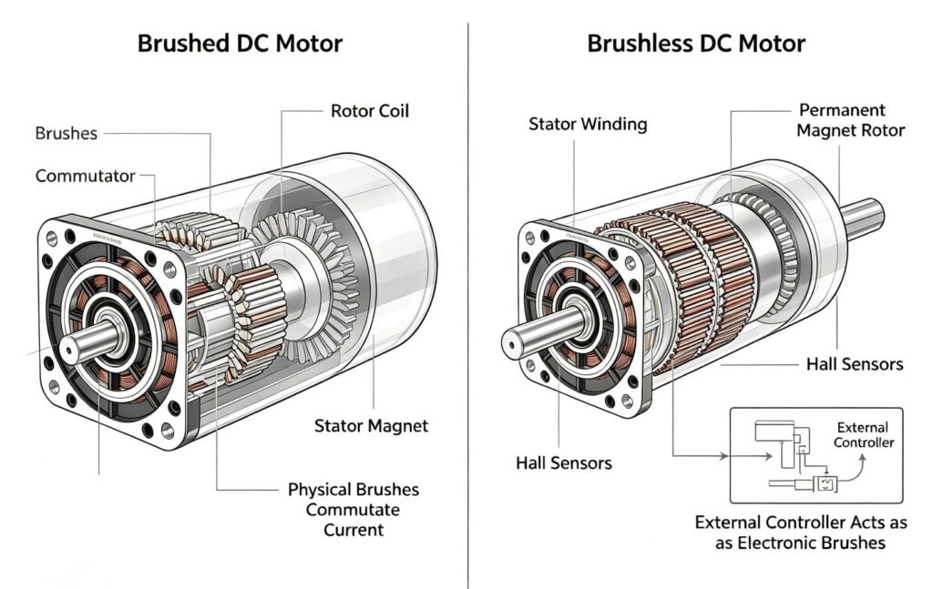
Brushed DC motors commutate mechanically, using brushes and a commutator. BLDC motors have no brushes. Instead, they rely on electronic commutation to switch current through the stator windings in the correct sequence. This job falls entirely on the controller. A three-phase bridge circuit and precise switching timing keep the rotor turning smoothly.
Without a properly matched controller, a BLDC motor won’t run efficiently, or may not run at all. It can overheat, lose torque, stall under load, or fall out of sync entirely. None of these are motor defects. They’re controller mismatches. The controller isn’t an accessory sitting beside the motor. It’s the interface between electrical power and usable mechanical motion, and it’s usually the first place to look when a motor underperforms on paper specs.
2. How BLDC Motor Controllers Work
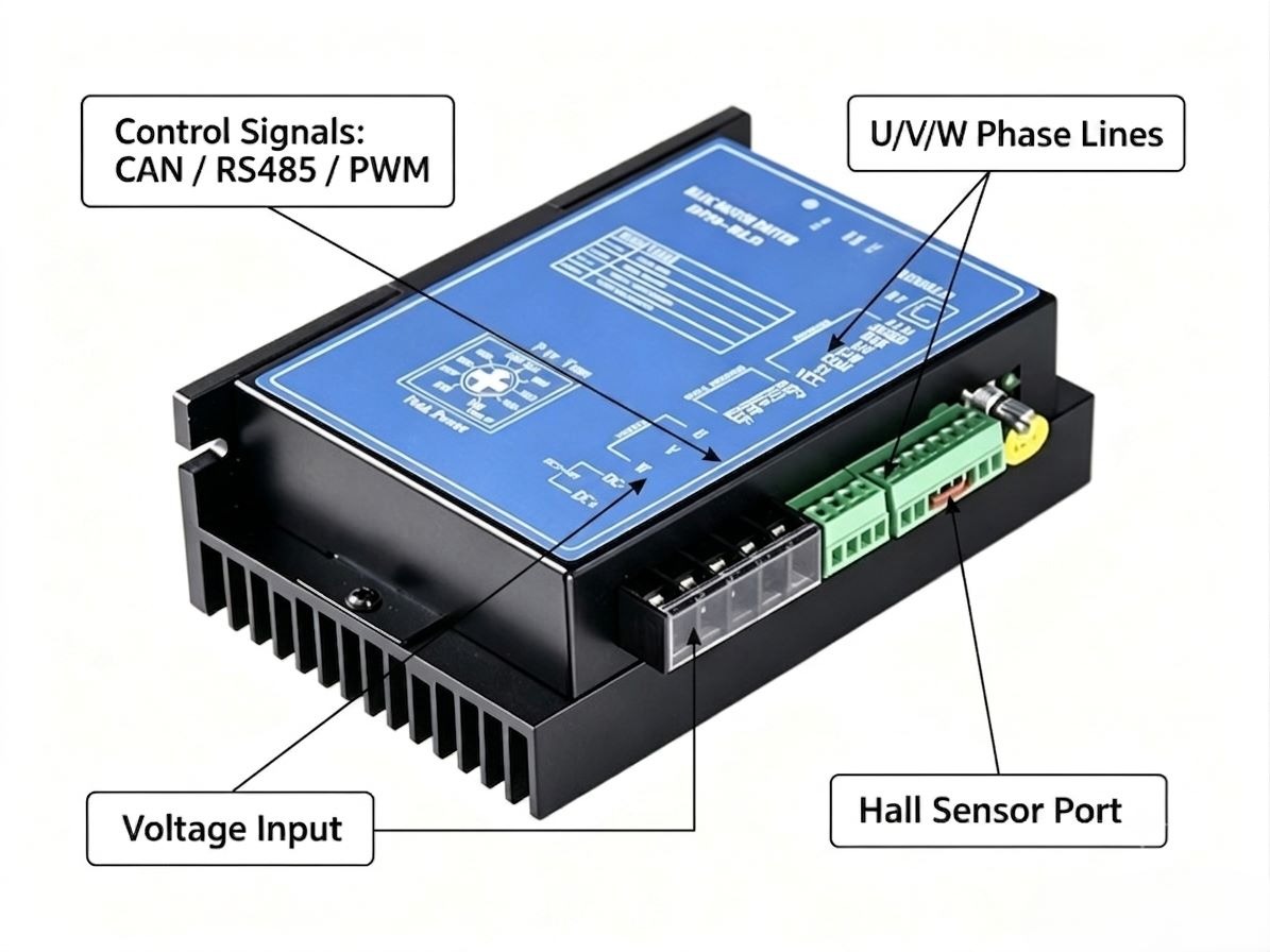
At a basic level, a controller does three things: it commutates the motor electronically, regulates speed through PWM, and protects the system from electrical and thermal faults. Some controllers also add closed-loop feedback, running as a full field-oriented control (FOC) system, but the three functions above are the baseline every BLDC controller has to handle.
Electronic commutation. Most controllers use six-step, or trapezoidal, commutation. Hall sensors, when present, report the rotor’s position so the controller energizes the correct winding pair at the right moment.
PWM speed control. Speed is adjusted by varying the width of the voltage pulses sent to the motor, not the switching frequency itself.
Current regulation and protection. Reliable controllers monitor current continuously and throttle back or shut down before overcurrent, overvoltage, or overheating causes damage.
BLDC controller vs. ESC. The two terms overlap but aren’t identical. ESC, or Electronic Speed Controller, usually refers to lighter-duty, high-speed applications like drones, e-bikes, and RC vehicles, where fast throttle response matters most. BLDC motor controller is the broader industrial term, covering everything from precision robotic actuators to conveyor drives, often with closed-loop feedback, communication interfaces, and rugged enclosures. For industrial durability and control flexibility, look for a controller built for that purpose, not simply an ESC.
3. Key Parameters When Selecting a BLDC Controller
Matching a BLDC motor controller to your motor and environment comes down to a handful of specs.
|
Parameter |
What to check |
|
Voltage rating |
12V, 24V, 36V, 48V, 60V, 72V, or 96V; match your motor’s nominal voltage with headroom for battery peaks |
|
Current rating |
Continuous and peak current; size for stall current plus a safety margin |
|
Heat dissipation |
Adequate heat sinking or fan cooling for continuous duty |
|
Control interface |
PWM, analog, RS485, or CAN, depending on how your system sends commands |
|
Motor compatibility |
Inner-rotor or outer-rotor, sensored or sensorless |
|
Protection & diagnostics |
Overcurrent, overvoltage, thermal cutoff, and fault reporting |
Getting these six items right up front avoids most of the troubleshooting that shows up later on the bench. It’s worth checking voltage and current together rather than separately, since a controller rated correctly for one but not the other will still underperform or fail prematurely.
4. Sensored vs. Sensorless BLDC Controllers
Sensored controllers use Hall sensors to know rotor position at all times, even at zero speed. That gives smooth, reliable starts, which matters for robotic arms and precision positioning. The tradeoff is extra wiring and one more potential failure point.
Sensorless controllers estimate rotor position from back-EMF instead. They simplify wiring, lower cost, and perform well at higher, steady speeds. The tradeoff shows up at startup and low speed, where control can feel less smooth.
If your application needs strong starting torque or fine low-speed control, sensored is the safer choice. If it runs mostly at higher, steady speeds and simplicity matters more, sensorless is often the better fit. A robotic arm that must start and stop precisely at any position benefits from sensored control, while a fan or pump running at a steady set speed rarely needs it. Some newer controllers detect motor type automatically and support both modes, which is worth asking about if your application spans both scenarios.
5. BLDC Controllers in Robotics and Industrial Automation
Robotic arms and actuators. Precision matters most here. Sensored controllers with tight current regulation deliver the smooth, repeatable motion that pick-and-place and assembly tasks demand. Repeatability, not top speed, is usually the deciding factor in this category.
AMR and AGV platforms. Mobile robots need a wide voltage range and stable performance across varying battery charge levels, plus reliable low-speed control for navigation and obstacle avoidance. A controller that performs consistently as the battery discharges over a shift matters more here than peak output.
Industrial automation equipment. Conveyors, packaging lines, and custom machinery benefit from rugged protection features and communication interfaces like RS485 or CAN for integration into larger control systems. Uptime and fault diagnostics tend to matter as much as raw performance in this setting.
Drones and UAV systems. Lightweight ESCs prioritize fast throttle response and low weight over the industrial features above. This is a smaller share of most industrial buyers’ needs, but it’s a useful reference point for how differently these controllers are optimized once weight and speed, rather than durability, become the priority.
6. How to Match a BLDC Controller to Your Motor
Before finalizing a setup, check the following:
● Voltage compatibility between motor and controller
● Current rating covers both rated and peak motor current
● Speed range aligns with the motor’s KV rating
● Torque and load requirements fall within the controller’s capability
Most field issues, like incorrect phase sequencing or loose Hall sensor wiring, show up as jerky motion or a motor that won’t start. For example, a 24V BLDC motor paired with a 48V-rated controller may run, but it will rarely deliver the response or efficiency the motor is capable of.
Working through this checklist before installation, rather than after a motor is bolted into a finished assembly, saves time and rework later. When sourcing standard-voltage motors or generic controllers to build out your system, platforms like Brushless.com offer a comprehensive selection of modular hardware to keep your prototyping both flexible and cost-effective.
Conclusion
A well-matched BLDC motor controller is the foundation of any reliable motion system. Motor and controller together, not either alone, determine how a machine performs in the field. Take the time to match voltage, current, and control interface to your application before committing to a design. The payoff is a system that runs efficiently and predictably for years to come, with fewer surprises once it’s carrying real load in the field.


More Stories
How to Choose the Right Air-Cooled Industrial Water Chiller for Manufacturing Applications
Why Power Quality Matters in Smart Manufacturing: The Role of Three Phase Voltage Stabilizers
Why Multi Gas Detectors Are Essential for Modern Automotive Manufacturing Facilities